|
|
Post by sigmfsk on Apr 18, 2012 17:26:13 GMT -5
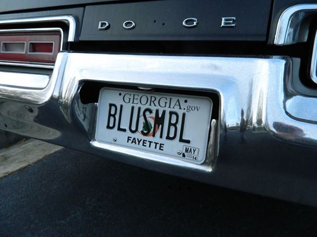
I am finding it difficult to convince helpers, who are body men by profession, to NOT smooth out every little dent. hehee. You need to be like blusmbl. You need to take out the dents so that you can put them back in. > Arthur, this may become a test part for your custom center caps. Lets do some chatting about this. I have a 9 1/4 in the Fury, and I'm guessing its in better shape than yours. I need an axle shaft (to use as a pattern for wheel spacers), but yours fit that need. We could trade shafts, or maybe you could use my whole 9 1/4. Options abound; this Fury isn't going anywhere soon. |
|
|
|
Post by spanks79 on Apr 18, 2012 20:30:06 GMT -5
I am finding it difficult to convince helpers, who are body men by profession, to NOT smooth out every little dent. hehee. You need to be like blusmbl. You need to take out the dents so that you can put them back in. Funny you say that. I just had that exact conversation today in reference to blusmbl's build. My buddy said " hay, just let me do my thing and I'll let you go at it with a ball bat before we spray the final coat of paint." If you want to do a deal on the axle shaft that would be great ( actually I was hoping you would say that as my search for lone axle shafts came up short earlier today). There seems to be a market for aftermarket shafts in the 4x4 market, but that would leave me with the same problem you have with an incorrect looking center register. Just a shaft will do, my housing will get scrubbed and blasted, so I think it should be fine, the carrier, bearings and gears are all going to be replaced. We can chat details off line. |
|
|
|
Post by blusmbl on Apr 19, 2012 7:49:42 GMT -5
Wow! This build is looking great! I better get to posting more pics as yours will be finished in no time  . The floors look really nice in POR-15 as well as the firewall paint. I can understand about the dents, the guys at work that would see the pics kept telling me to stop doing bodywork on it because it was supposed to be a sh*tbox Dodge. When I put the dents in mine I had a heart to heart conversation with the car about where they were going and why as I was hitting it  |
|
|
|
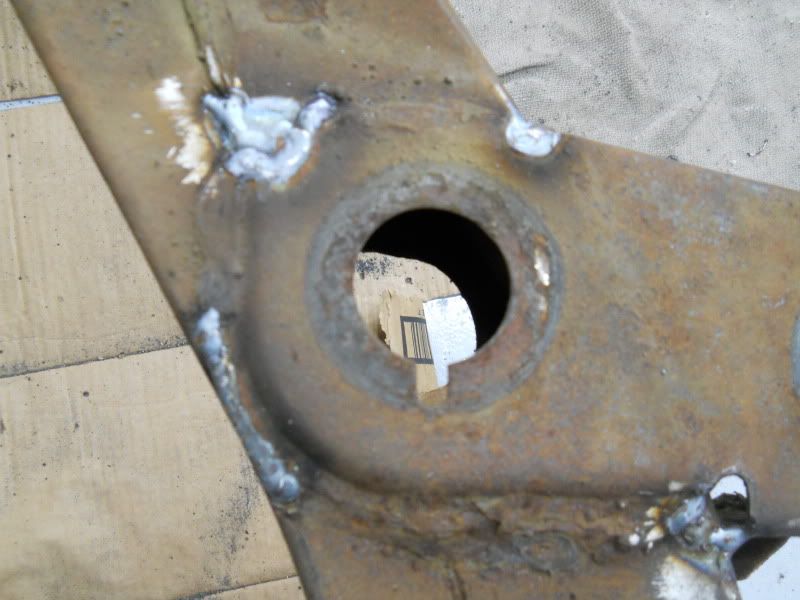
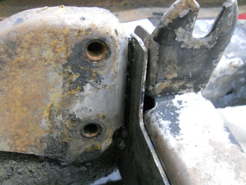
Post by spanks79 on May 15, 2012 21:49:21 GMT -5
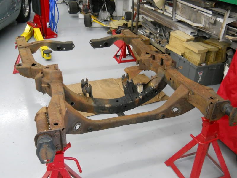
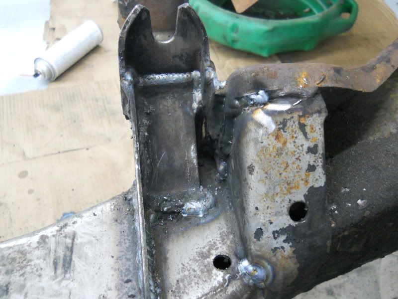
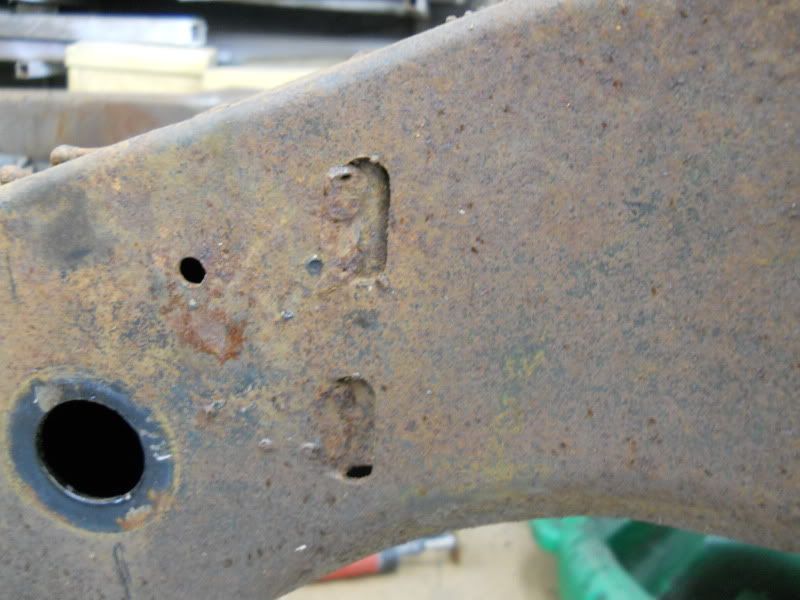
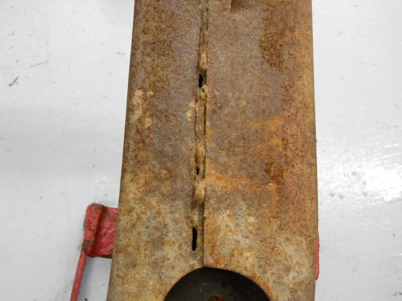
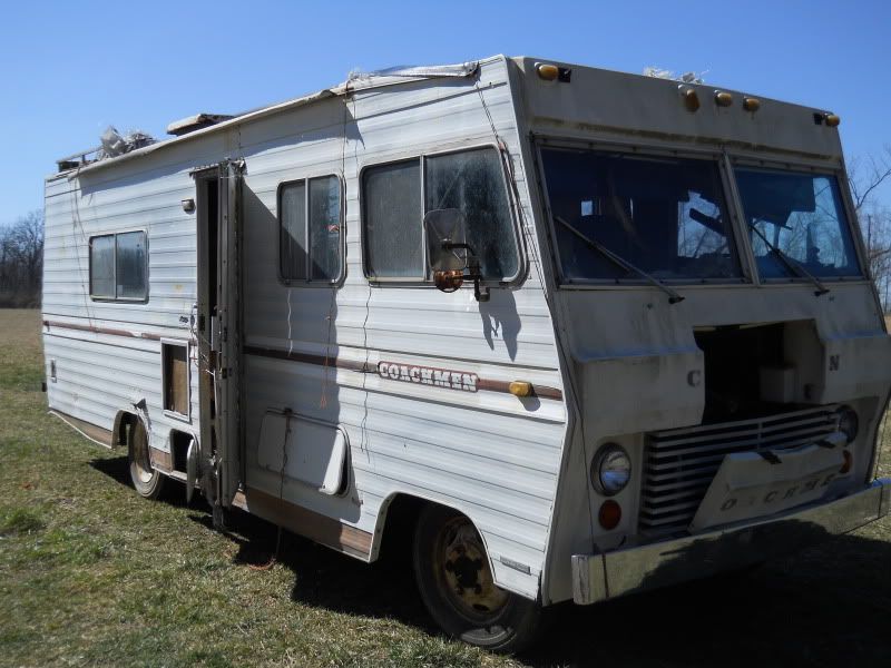
It's been a few weeks since I have posted an update, but never fear I am still working. I don't have a lot of pictures but the body shell is still in process, getting ready for primer soon. I did sort thru a bunch of parts. I got the sub frame stripped down, here is the before 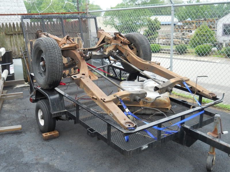 I plan on cleaning up the sub frame a bit, touching up the half a$$ welds and then sand blasting and paint. I will post pics of this process. I figured out which gas tank to use. The one from the MI car was wasted, the one from the NC car was really nice inside, like new kind of nice, but had a big dent. 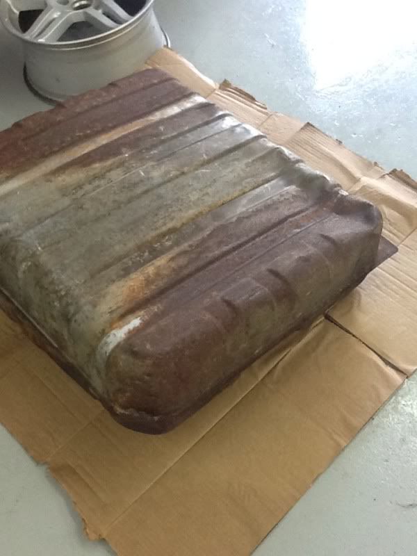 I am slowly working this out, it won't be perfect but it will look nice and save me some cash over replacing it with a new one. I collected up all my fuel and brake lines and sent them off to www.inlinetube.com where they are suppose to reproduce a complete set of lines that are exact copies of my originals. We will see how that turns out. I also got some chunks of Delrin that I plan on using to whittle out a set these 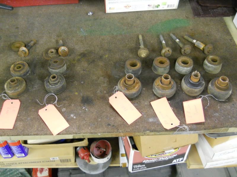 Finally, I placed a rather large order with Firm Feel to complete my suspension needs. Between what I have on order combined with what I bought from Arthur, that he was not going to use, I should have a pretty good handling Blumo. More pics to follow. |
|
|
|
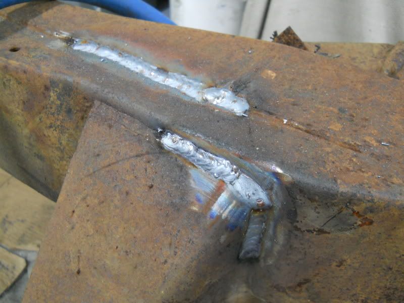
Post by spanks79 on May 18, 2012 6:57:13 GMT -5
|
|
|
|
Post by sigmfsk on May 18, 2012 7:49:47 GMT -5
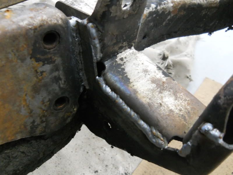
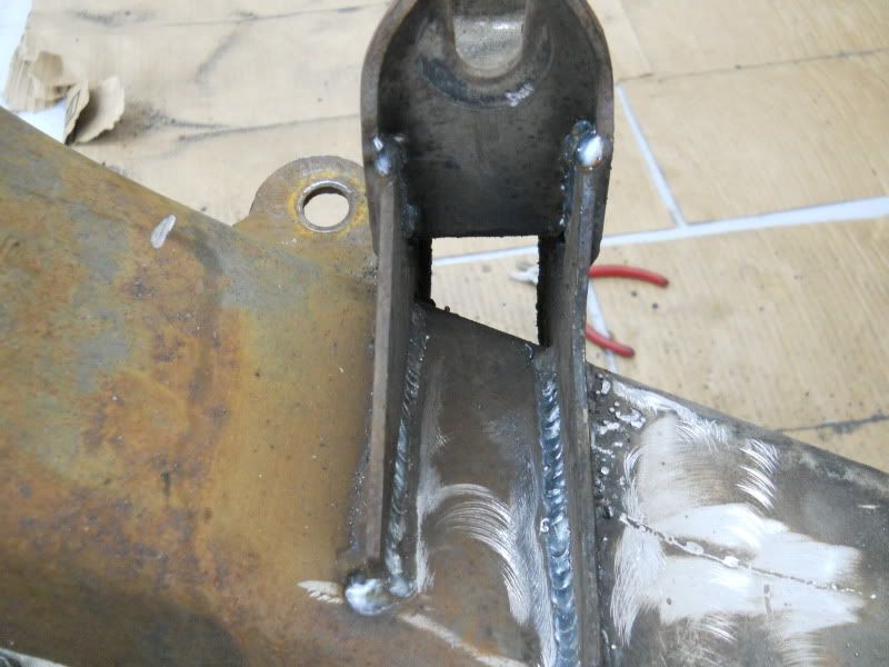
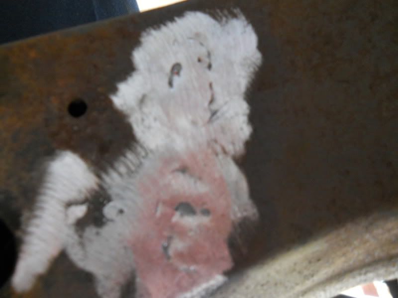
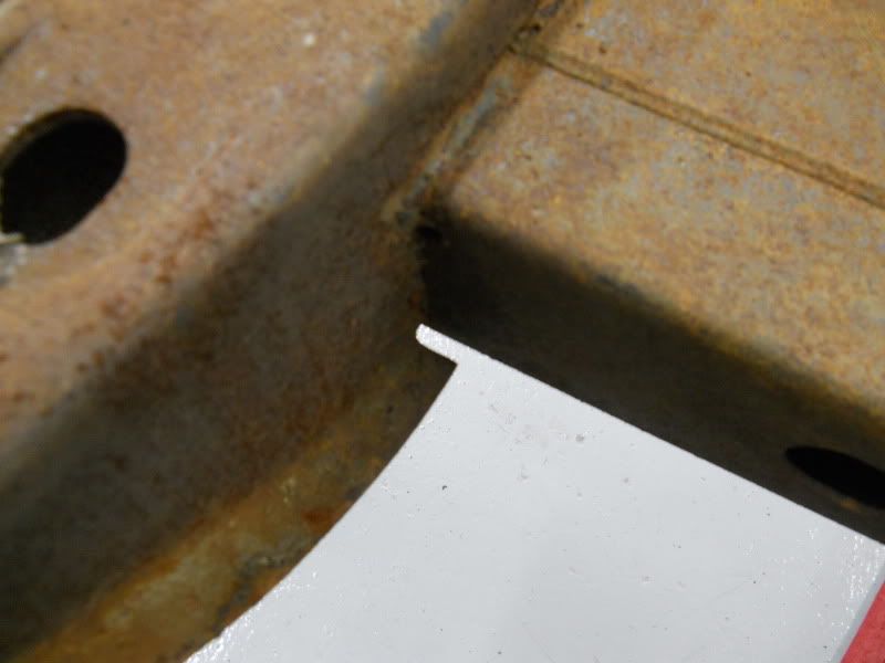
Motor mount was just spotted together 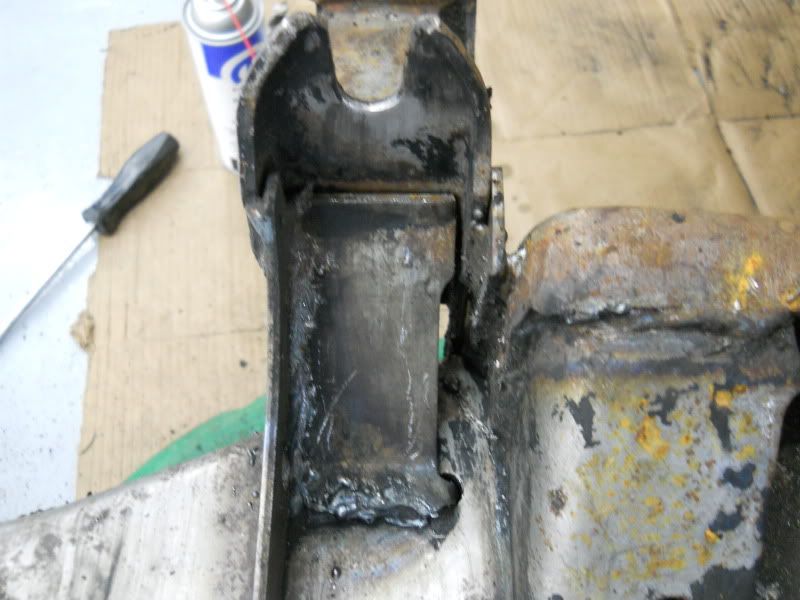 The "before" is just scary looking. Nice job on the afters! Now's the time to beef it up. Something you could also do is weld in plates like they did on the 77 (and maybe 76) cop cars, as in this thread: bluesmobiles.proboards.com/index.cgi?board=police&action=display&thread=521Maybe those plates only made up for the poor quality factory welds, and you've already done that. Or maybe they'll still add some rigidity. Your friend in a non-flexing subframe, arthur |
|
|
|
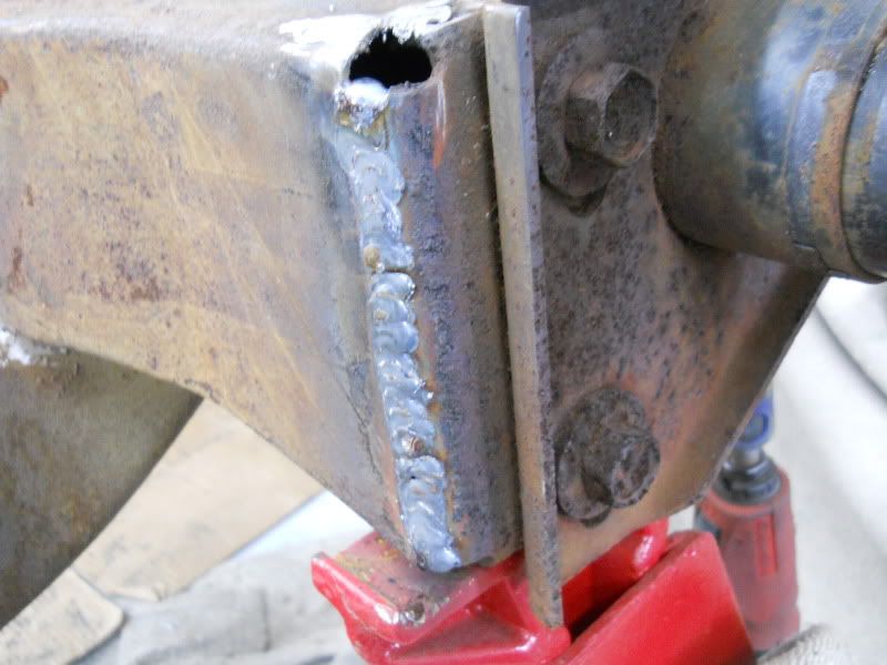
Post by spanks79 on May 18, 2012 19:36:29 GMT -5
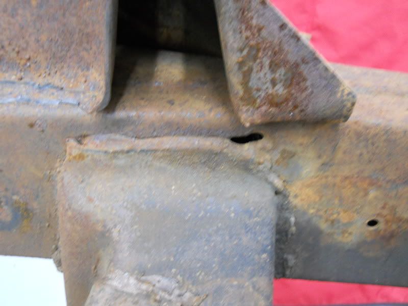
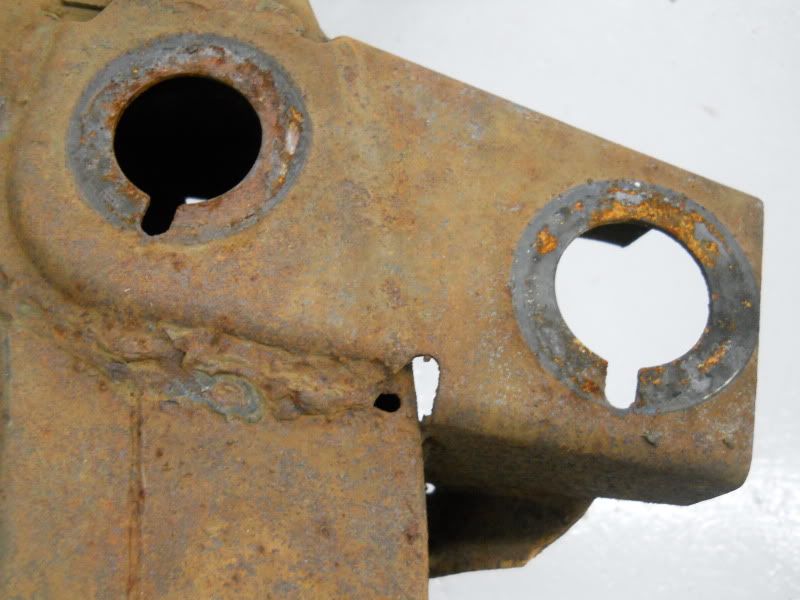
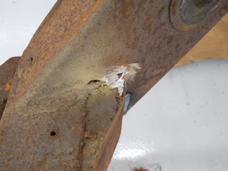
I was thinking of that, but wasn't sure if it would make that much difference. If I see the pictures correctly, it looks like the reinforcements entail 3 pieces. The angle on the lower inside edge of the frame rail, a plate on top of the frame rail, and finally a gusset of sorts that overlays the cross member where it attaches to the frame rails. Am I missing any others? The latter seems it would offer the most improvement in helping out the factory welds as evidenced by your badly cracked sub frame. |
|
|
|
Post by Mr Mercer on May 18, 2012 22:36:09 GMT -5
Maybe they were left like that from the factory so the sub frame could flex ?
|
|
|
|
Post by sigmfsk on May 19, 2012 7:06:48 GMT -5
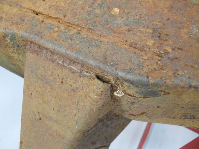
If I see the pictures correctly, it looks like the reinforcements entail 3 pieces. The angle on the lower inside edge of the frame rail, a plate on top of the frame rail, and finally a gusset of sorts that overlays the cross member where it attaches to the frame rails. Am I missing any others? The latter seems it would offer the most improvement in helping out the factory welds as evidenced by your badly cracked sub frame. I'm just going by pictures, but I believe your list is correct, and all the pieces are shown in the pic: > a gusset of sorts that overlays the cross member where it attaches to > the frame rails It does seem that this would be of use mostly to correct for any sub-par welds underneath it. But I suppose it might spread the load better. Those other pieces are puzzling. They wouldn't seem to add much strength other than just making the subframe thicker at those locations. But maybe Ma Mopar's motivation wasn't actually to add strength, but merely to show somebody that they'd done something that could plausibly argued to improve strength (maybe they just added them to get the coppers of their back). Or maybe it actually does something good that we're not catching. I think you're way ahead of the curve just by ensuring that the entire subframe is solidly welded. |
|
|
|
Post by spanks79 on May 19, 2012 18:18:09 GMT -5
Maybe they were left like that from the factory so the sub frame could flex ? I thought about that. I know all structures flex, but there does not seem to be any consistency it the welds that are there. It simply looks like the welders were in a hurry and just looking to get it good enough. Plus we have proof that they made an effort to strengthen the structure by adding the reinforcements. I looked at the sub frame today thinking about how I could add reinforcements. One possible conflict is the shift linkage skid plate. It sits flush to the bottom of the frame, adding an angle iron piece along the lower edge will cause a conflict, not a big deal, but I would be curious to see how the factory delt with that. Now that Arthur pointed it out, I feel somewhat compelled to add some reinforcement simply because I have the perfect opportunity to do it now. Some simple flat plates would be easy enough to do. Another thought as to why Ma Mopar added the reinforcements in the first place may have been "crashibility". In a frontal impact subframes like these tend to buckle and kink right in that kick down area where the angle and plate are added to the frame rail. I have seen frames like this hit so hard that the "kick down" portion of the frame is resting on the ground right behind the front tire. So the reason they were added may have been to allow for more aggressive pushing with push bars or to provide greater strength in significant frontal impacts. |
|
|
|
Post by sigmfsk on May 19, 2012 22:21:12 GMT -5
In a frontal impact subframes like these tend to buckle and kink right in that kick down area where the angle and plate are added to the frame rail. I have seen frames like this hit so hard that the "kick down" portion of the frame is resting on the ground right behind the front tire. So the reason they were added may have been to allow for more aggressive pushing with push bars or to provide greater strength in significant frontal impacts. Hi Spanks: That's a good thought. Maybe it wasn't solely for frame rigidity when not in an accident. It could have been for improved crashability when in an accident. It made me think of this pic I saw recently: from "How to build GM pro-touring street machines". Is it saying that in an accident, the standard frame bends at the kickdown, with the front of the subframe pushing up? And that with just a single downtube to the front of the subframe this type of bending would push the downtube brace through the firewall? And preventing that would be good (occupant survivability would increase if the subframe was strong enough to help prevent this collapse)? And the extra triangulation shown above helps prevent this collapse? It seems to me that if the subframe bent rearward of where the extra triangulation welds to the subframe, that triangulation doesn't help prevent the subframe from bending up. So I never really figured out the concept described by the caption. your friend in talking through various theories, arthur |
|
|
|
Post by spanks79 on Jun 4, 2012 22:36:50 GMT -5
Look what showed up today! 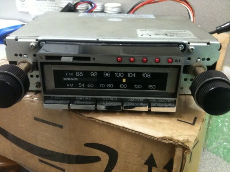 It looks really good. Very light use and very clean. It looks like it has hardly been used. I rigged up a speaker and some jumper wires to test it out. I was a little concerned about the eject mechanism as it wouldn't hold the tape in at first. That and Arthur said he had troubles with his 601 eject mechanism. I removed the cover and found the mechanism to be a little gummed up with 30 year old lube. A couple drops of oil in the right spots and she started working just fine. Needs a little cleaning and I think the belt may be slipping a bit. You will notice in the video that when I pushed the cartrige in it actually holds in so hard the tape cant move internally, I have to pull it out a bit to get it going. I got lots more good stuff going on, the ups man will be busy this week.  |
|
|
|
Post by Steam McQueen on Jun 5, 2012 20:44:36 GMT -5
Look what showed up today! Awesome! - This is awesome, too ... 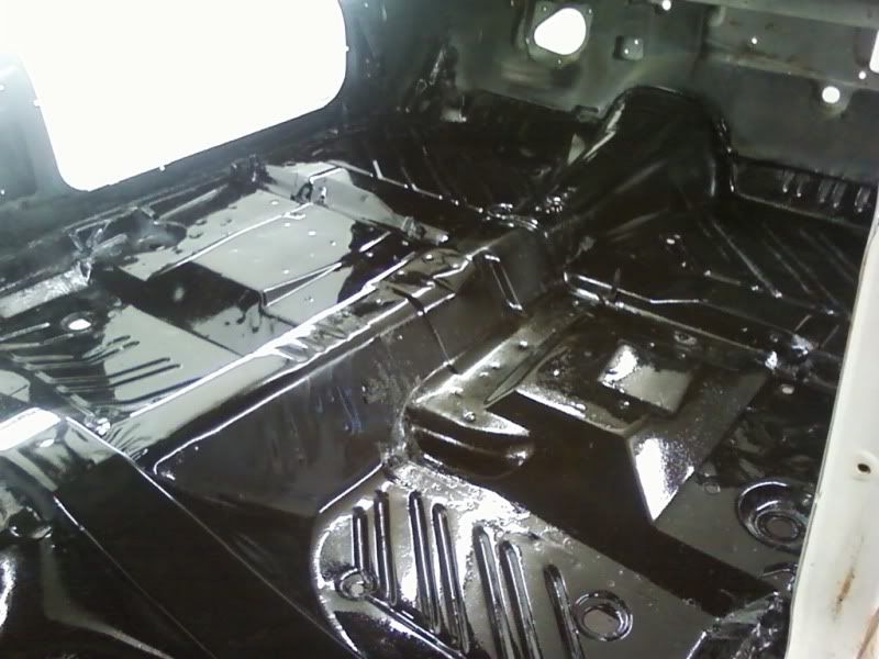  |
|
|
|
Post by spanks79 on Jun 5, 2012 22:57:57 GMT -5
Thanks Steam! I am trying to keep the awesomeness moving along! This is pretty awesome as well. Look at this box of stainless spaghetti I got today. 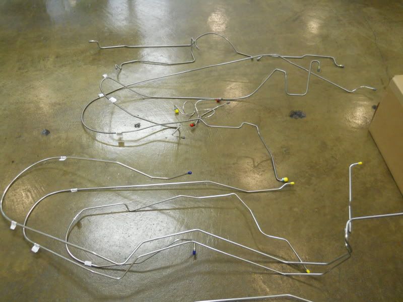 These are the reproduction brake and fuel lines Inline Tube made from my originals. They look fantastic! 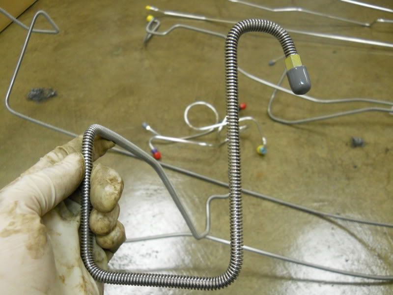 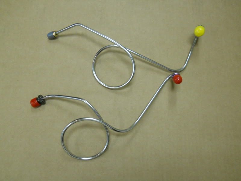 I just hope they fit well. If you google inline tube you will find complaints about fitment and what not, but these are suppose to be copies of MY lines and I understand the brake lines for 35 year old cars will not be an exact science, I imagine some tweaking may be required. Also they asked if they could keep my old lines for patterns, so hopefully in the process I am able to help out another fellow C body owner with some reproduction brake and fuel lines. Some other cool progress. Couple of transmissions off to the trans guy. The one on the right is out of the motorhome my 440 came out of, trans guy says it has heavier duty innards so he plans on building it and using the tail shaft off of the one on the left, which is the trans that came out of the white car. 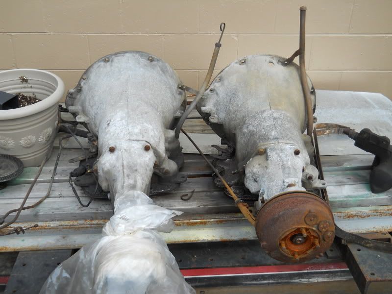 Oil pan off of the 400 out of the white car, cleaned up, straightened and leak tested (filled with solvent and let it sit for a few days). It had some dents and bumps on the bottom, plus we had a small "event" while removing the engine from the car that caused a dent or so. 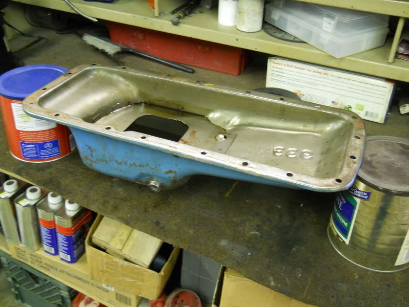 Finally some more progress on the body. Most of the rust repair is complete and body work on the quarters and roof complete with a full coat of primer. 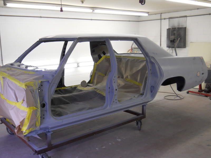 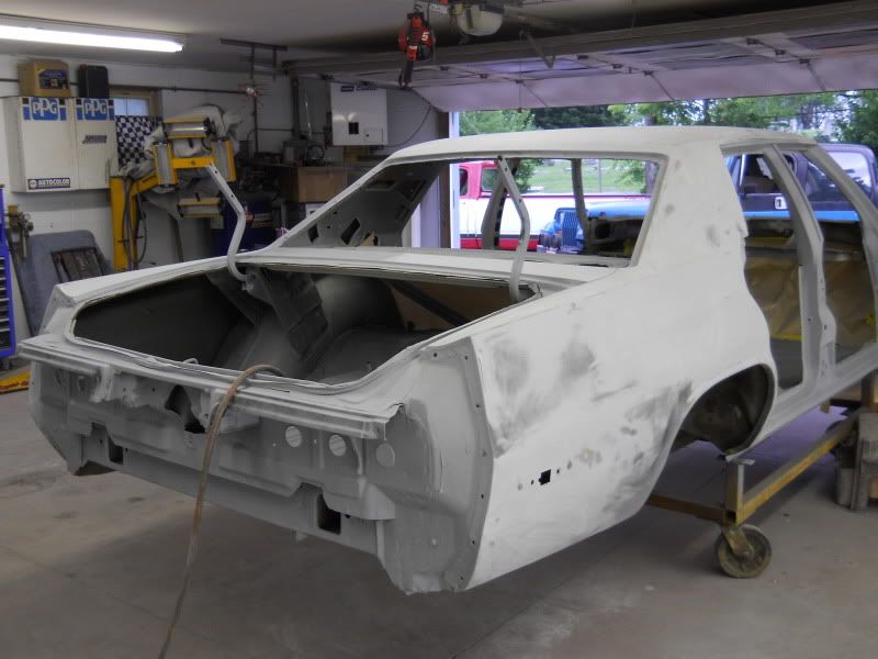 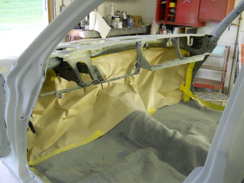 |
|
|
|
Post by sigmfsk on Jun 6, 2012 4:48:33 GMT -5
...these are suppose to be copies of MY lines and I understand the brake lines for 35 year old cars will not be an exact science, I imagine some tweaking may be required. Also they asked if they could keep my old lines for patterns, so hopefully in the process I am able to help out another fellow C body owner with some reproduction brake and fuel lines. Awesome, times two! Some good lookin' pics! |
|


 . The floors look really nice in POR-15 as well as the firewall paint.